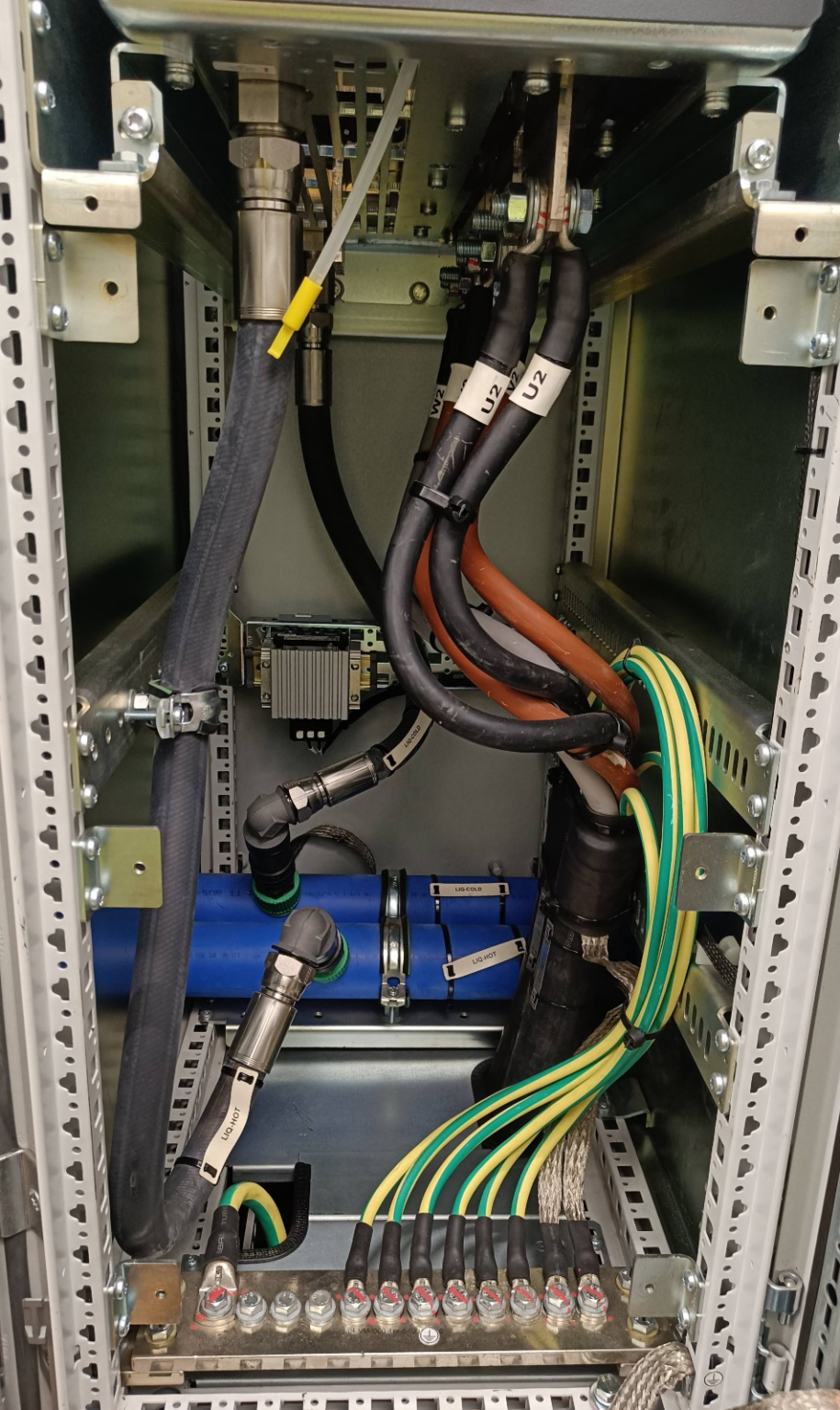
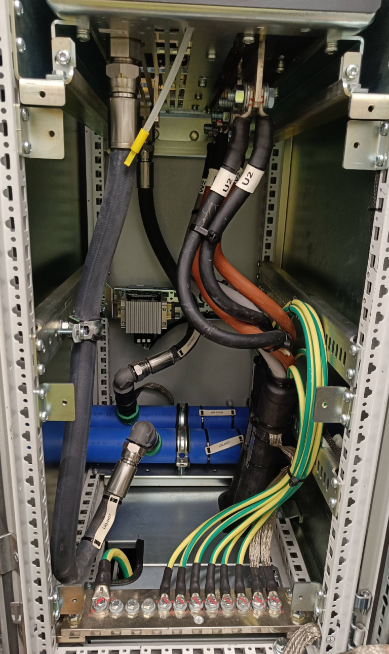
Traditional Grounding Techniques Fail our Electric Motors!
Common practice among electricians suggests that grounding should be approached similarly to protective earth (PE) connections, typically involving the use of green-yellow wires with substantial cross-sectional areas, distributed liberally. However, grounding to avert bearing currents in electric motors requires a distinct methodology.
The key is to establish a low impedance pathway from the electric motor’s stator to the variable frequency drive’s ground. This ensures that the bearing currents are adequately diverted, preserving the bearings’ integrity and prolonging their operational life.
Notably, this pathway must be consistent and free from high impedance caused by the skin effect—a phenomenon where high frequency currents tend to flow on the surface of the conductor, avoiding the core, which is more pronounced in conductors with larger cross-sections.
To establish an effective grounding path, it is recommended to use materials that are both thin and highly conductive, such as braided earthing tape, which offers a large surface area for efficient current distribution. Additionally, incorporating low impedance connections like EMC (Electromagnetic Compatibility) brackets and EMC glands is crucial. These components work together to provide a smooth and reliable grounding path that minimizes the risk of bearing currents.

Key Insights:
- Grounding serves a different purpose than protective earth.
- Simply adding more grounding points is not effective; the path must be consistent.
- High frequency grounding demands specialized materials to circumvent the skin effect and secure low impedance.
By understanding and implementing these principles, we can ensure that our grounding methods are not only compliant but also effective in protecting sensitive electrical equipment from bearing currents.


